Difference between revisions of "Cell Imaging Using Picosecond Ultrasonics"
(→Instrument) |
(→Instrument) |
||
| Line 4: | Line 4: | ||
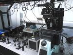
description of the ASOPS pump probe system and figure. | description of the ASOPS pump probe system and figure. | ||
| − | [[Image:BNC_ASOPS_Layout.jpg | | + | [[Image:BNC_ASOPS_Layout.jpg |150px|alt=alt text|ASOPS pump probe instrument]] |
<br style="clear:both" /> | <br style="clear:both" /> | ||
Revision as of 06:31, 18 October 2013
Contents
Motivation
Instrument
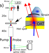
description of the ASOPS pump probe system and figure.
Detection mechanism - Brillouin Oscillations
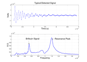
The probe light is reflected from the sample surface to the detector, and if the sample is transparent there is also a reflection from the acoustic wave packet traveling in the sample. This happens because the acoustic wave causes a change in the local refractive index and so acts as a weak mirror. These reflections interfere at the detector and as the phase of the reflection from the acoustic wave is changing with time it leads to an oscillating signal. These oscillations are termed Brillouin Oscillations.
The frequency F of the oscillation is given by the simple equation: F = 2*Va*n/λ
So if we can measure this signal we can measure the acoustic velocity Va, as long as we know the laser wavelength λ and the refractive index n.
Substrate Design
 |
|
 |
|
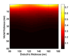
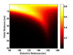
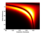
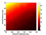
the cells are grown on a transducer substrate similar to those described here. The optimization of the transducer layer is different in this case. Here we are much more concerned with optimizing the optical properties of the transducers. The goal is to reduce the amount of blue light reaching the cell and either maximize the reflected or transmitted light, depending on the experiment requirements. We still have to take care that the acoustic performance of the transducer is good and that the acoustic bandwidth is sufficient to generate waves at the Brillouin frequency.
Example results
|
|
Publications and Talks
IOP LU2013
